Velo3D
Significant growth in new automotive platforms—from 200 models ten years ago to potentially 480 by 2029, according to AutoForecast Solutions—will drive strong increases in tooling investments by the industry, says Harbour Results Inc. Expected to grow 13.4% year-over-year, from 5.7 billion in today’s dollars to 8.3 billion in 2025, the rise in demand for novel car models will require all-new tooling, no matter the volumes of production, due to standardized requirements for fresh exterior and interior designs.
A significant proportion of vehicle model and tooling growth will come from battery electric vehicles (BEV), rising from 20% of the market this year to 46% in 2029, Harbour Results anticipates.
Additive Manufacturing (AM) offers new tooling solutions
The vehicle industry is in a very dynamic state. Many breakthroughs and manufacturing advances will be required to keep such investments on track in terms of improved efficiency, throughput, and profitability. The industry’s growing interest in metal Additive Manufacturing is an example of such a focus.
Recent advances in Laser Bed Powder Fusion (LBPF) are now providing unparalleled design freedom, larger-capacity print volumes, advancements in automated calibration routines, and scalability. Tooling is a distinct area that can benefit from AM’s enhanced capabilities.
Design freedom leads to production efficiencies
Those who work with high-pressure die casting (HPDC) or injection molding (IM) machines know the importance of cooling for better part quality, reduced cycle time, and improved final yields. Conformal cooling is a technique used to accelerate and control temperature declines in tooling inserts (and sometimes in new core and cavity designs).
In aluminum die casting, for example, the molten metal arrives at the die at a temperature of around 600°C or more and injects into the part cavity in about 20-milliseconds. The part then solidifies with the help of liquid flowing through cooling channels that surround it, decreasing in temperature to approximately 60°C within 60 seconds or so, depending on the part solidification strategy.
When the injected component has solidified, the die separates and pins eject the part from the die. In die-cast production, cooling of the die-cast insert constitutes around 70% of the cycle time to manufacture a part. By accelerating the cooling rate, tooling designers can speed-up production times. They can also increase the lifetime of the cooling inserts and even can improve the material properties of the end-use part.
Conformal cooling has been around for a while. In fact, in principle, it is similar to a solution used in spacecraft design—regenerative cooling.
In regenerative cooling, cold fuel flows through a rocket nozzle to prevent the nozzle from melting. The result is a nozzle that is cryogenically cold on the exterior but experiencing full rocket exhaust combustion on the interior. Engineers have found such solutions to preserve their parts’ survival even when exposed to environments that exceed the melting point of the metal.
Design solutions similar to those used to launch spacecraft are now being used in automotive plastic-part production.
Past challenges of manufacturing cooling channels
Engineers have limited design freedom to create cooling channels when using conventional manufacturing methods. Most approaches involve drilling (or sinking EDM) straight, intersecting lines for cooling fluid to flow through. However, this type of cross drilling can cause several issues like stress concentrations and leaks.

Image 2. Traditional approaches to creating cooling channels are not fully optimized and have sharp corners and blind holes that can lead to mold stresses and inconsistent part formation.
In addition, since these cooling channels are formed in straight lines, hotspots often remain out of the coolant's reach. The thickest parts of the casting that also have the longest solidification times—along with high-aspect ratio features such as pins—do not see optimized cooling amounts. Since these sections take the longest time to cool, speeding up the process in these areas can help accelerate the entire manufacturing process. It can also mitigate the risk of opening the die too soon and exposing molten metal to the atmosphere.
Conforming makes the difference
In contrast, metal AM can be leveraged to print an insert with conformal cooling channels that follow the contours of a part and provide more optimized cooling. By integrating conformal cooling channels, manufacturers can achieve a number of beneficial results:
● Reduced cycle times (time per shot goes down)
● More uniform temperature gradients to eliminate hot spots
● Better, more complex designs that improve the material properties of die-cast parts

Image 3. A conformal cooled tooling insert of a working surface for high pressure die casting. Image courtesy of Velo3D.
With conformal cooling, it not only becomes possible to optimize manufacturing, but engineers may also be able to thermally balance the tool, resulting in a casting that solidifies near-simultaneously.In casting, the last sections to solidify also tend to have a higher concentration of air pockets. By creating a cooling strategy that solidifies the more critical sections faster, conformal cooling can help to move these air pockets away from harmful areas. By controlling the cooling balance, engineers can improve the material properties of their parts.
Higher production, lower insert costs
One of the past roadblocks that has held back AM in cast/mold production has been limited printer sizes and corresponding build volume. These issues are quickly being overcome as increasing numbers of large-format, multi-laser printers have entered the market.

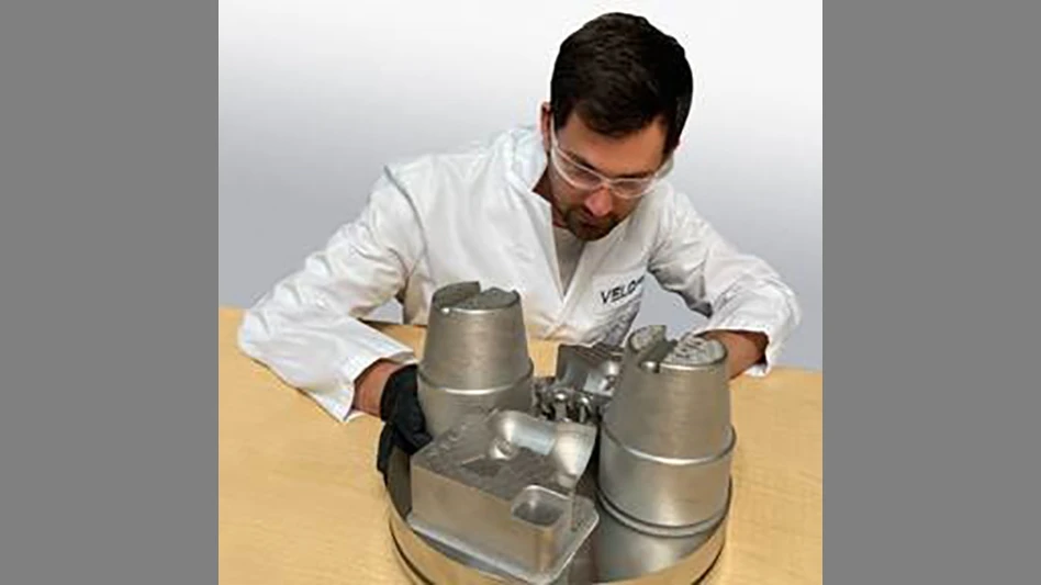
Image 4. An M300 tool steel print of multiple conformal-cooling tooling and high-pressure die casting inserts. The parts are shown as printed on the build plate. Image courtesy of Velo3D.
The growing dimensions of metal 3D printers increases the opportunity for creation of larger diecast inserts. The likelihood of additional lasers also has the potential to accelerate the die-insert manufacturing process and lower insert costs.
What’s more, engineers are now examining the possibility of increasing cooling-channel size and cross-section design. And this is where many current AM technologies struggle: for channel cross-sections larger than ~6mm in diameter, inserts have started to experience premature failures.
You can design what you want, but can you print it successfully?
Some of these failures have been due to the challenges inherent in conventional metal AM systems.
Metal additive manufacturing, specifically Laser Powder Bed Fusion (LPBF) printers, deposit a planar surface of powdered metal onto a build plate. The lasers inside the printers then follow a two-dimensional pattern of one layer of the part, melting the metal powder in specific locations dictated by the design. The metal then cools and solidifies quickly.
As the metal cools, it contracts. When printing layer after layer, this process of melting and cooling builds stress. This stress, and the need to remove heat from the melted layers, can result in potential deviations from the design.
There's a higher frequency of deviations on channels of any kind. A circular channel, printed layer by layer, results in two sides—or curved walls—of a cylinder that must eventually meet and close out at the top. During this close-out the stress on these two walls is the greatest, leading to deformation in the structures.
The result is a channel with a non-uniform, upper close-out section with poor surface finish. A rough finish results in stress concentration, eventual cracking of the part, and premature failure.
 Image 5. A test sample of different-diameter (millimeter numbers at lower edges) cooling channels, successfully 3D printed on a Velo3D Sapphire AM system in M300 tool steel and cut in half to show interiors. There is no significant erosion of the downskin surfaces, even at the 40mm + diameter profile (channel at far left); this is important because significant erosion of the downskin in a printed channel will contribute to crack initiation sites. Image courtesy of Velo3D.
In addition, with more lasers comes the potential for each laser to drift out of alignment with the others. Conventional systems require a complex, manual calibration process involving external equipment and testing routines. Typically, due to the manual and time-consuming nature of the calibration, operators only adjust the lasers a few times a year. This leads to drift over time and within the build if the chamber temperature rises and components shift. As a result the overlay—the area where the two laser zones meet—can become compromised during the print, leading to weak points in the part.
A big leap in channel dimensions
Advanced, next-generation AM systems offer a solution on several fronts. With larger build plates, engineers can access larger-format printing for their die inserts.
Automated calibration routines and runtime layer-by-layer calibration checks ensure virtually invisible overlay zones.

Image 6. Velo3D offers one of the largest metal 3D printers in the industry with the Sapphire XC 1MZ with a 600mm Ø x 1000mm Z build volume that enables the manufacturing of larger molds and inserts up to 600mm. Featuring 8 lasers with seamless overlay, this system is capable of printing high-quality mold inserts at much higher throughput than current standards. Image courtesy of Velo3D.
Perhaps most significantly, engineers can now realize circular channel cross-sections at significantly larger diameters. The most highly integrated AM systems are capable of printing channels up to 100 mm in diameter with a quality surface finish; a full order of magnitude beyond what exists in the industry today. This capability helps to mitigate local accumulation of stress that is common on the teardrop shape typically produced in the design-for-additive manufacturing (DfAM) process.
Integration of pre-print design software and printing hardware largely avoids the design compromises and part defeaturing endemic to the DfAM approach. This new level of attainable design sophistication and performance works to eliminate the risk of cracking. It also serves to optimize the flow of the coolant (water/oil) and achieve higher heat-dissipation rates.
The future of metal AM for tooling
Advanced metal AM systems will be the main driver of future tooling innovation due their powerful, integrated, end-to-end solution sets serving both part and tool optimization. These solutions are comprised of sophisticated pre-print design software; high-capacity, highly accurate printing; and quality-assurance software for in-situ monitoring and quality-control reporting—all on a unified platform.
Such solutions translate into the time-saving ability to automatically assign geometry-specific scanning instructions, for example. This produces a robust printing process yielding a higher-quality surface finish and consistent mechanical properties without compromising the design. It also gives non-AM experts confidence that their designs will print to the standards they require for both simple and complex parts and tooling.

Image 7. High pressure die casting insert to support the manufacturing of automotive components. Image courtesy of Velo3D.
While growth in any industry is never guaranteed, fast-advancing technology and new-model trends in vehicle development seem inevitable from both a consumer and governmental standpoint. Improved HPDC and IM tooling performance, achieved through advanced AM, will help launch and sustain future vehicle platforms—more efficiently and profitably.
Latest from EV Design & Manufacturing
- Powering homes with EV batteries could cut emissions, save thousands of dollars
- Meviy introduces stainless steel passivation option for CNC, sheet metal parts
- December Lunch + Learn webinar with Fagor Automation
- December Lunch + Learn webinar with LANG Technik + Metalcraft Automation Group
- EVIO makes public debut with hybrid-electric aircraft
- Redesigned pilot step drill triples performance
- Green Energy Origin expands battery electrolyte manufacturing in North America, Europe
- What’s next for the design and manufacturing industry in 2026?